DIY Solar Powered Remote Timelapse Camera with 4G LTE

My wife and I are in the process of building our house. I knew from the beginning that I wanted to timelapse the build. The idea of making a video of “5 months in 2 minutes” is really interesting to me. So I got myself an off-the-shelf construction timelapse camera. Tested it out, and the quality was disappointing. I suppose being a wedding photographer I demanded more from a photography project. So I did what any tech nerd photographer would do – I built my own timelapse rig! Except this time I one-upped it and added solar power on a timer, with a wireless AP and 4G LTE modem. This allows for instant uploads to my computer.
This post is my attempt at documenting as much as I can about the build. Hopefully it helps someone out who attempts to build their own one day.
Synopsis (aka tl;dr):
The whole thing is powered off a 30 watt, 10Ah solar system. There’s a DC timer that runs the system for 9 hours a day, 6 days a week. Using “hacked” firmware on the Canon point and shoot camera allows for automatic photos every 7 minutes. The photo then gets saved to an Eye-Fi SD wifi card. The Eye-Fi is WiFi connected to the WiFi AP. The AP is connected to the internet via 4G LTE Verizon card. Eye-Fi uploads every photo via FTP to my house, where I can view and archive the photo. End goal: a low maintenance timelapse setup which will allow us to create a video of our house being built. “5 months in 2 minutes.”
Sections:
- Step 1: Hack the camera
- Step 2: Get the AP and 4G LTE setup
- Step 3: Time to hack the hardware
- Step 4: Figuring out solar power
- Step 5: Mount it in the field
- Step 6: Final steps
- Lessons learned
Materials needed:
- A Canon point and shoot camera that’s on the CHDK compatibility list. I chose the Canon PowerShot ELPH 130 IS.
- An Eye-Fi WiFi memory card
- A TP-Link MR3020 Wireless Router
- A waterproof case. I chose Nanuk 903 in Olive.
- Some glass to attach to the case. I chose some UV filters since they were already cut in a round shape.
- A dummy battery for the Canon camera so that it can be powered by the wall.
- A small quick-release tripod mount so the camera can be removed from the case if needed.
- A 12V DC Timer to save on battery life
- A low power wireless AP that can run OpenWRT (Linux) and allows for 4G LTE USB Cards
- A USB 4g LTE modem. I went with the Verizon 4G LTE USB Modem UML295 without a contract
- A container of Marine Goop
- A DC voltage converter. To make it easier for me, I bought this one which is a little overkill.
- A package of waterproof glands to allow cables to pass into the case.
- A 30 Watt Solar Panel. More on this later
- A solar charge controller.
- A 12V DC 10AH battery. More on this later, too.
- A ladder (optional, but recommended).
- A bunch of 1/4-20 screws
- 5 or more rubber washers that fit the 1/4-20 screws
- A heavy duty corner brace to mount the quick-release tripod mount to
- Some strips of heavy duty velcro
- Various other bits and bops covered throughout the tutorial
Total cost:
I didn’t want to put values on every line item above, because chances are it’ll all change. At time of writing, everything documented here cost me around $500. I built this over the course of 4 months. The total cost includes buying the Verizon Wireless USB modem without contract, the solar panel, the battery, the Canon camera and the Eye-Fi 16GB Pro SD card.
Step 1: Hack the camera
I decided to go with a Canon point and shoot camera for a couple of reasons. The point and shoot will have much more megapixels than that off-the-shelf model, but the real reason is control. The firmware can be “hacked”, which would allow for automatic timelapses using an addon script. Using CHDK (Canon Hack Development Kit), you can get much more control out of the camera. You aren’t hacking the camera firmware per se, but really overriding the camera’s firmware with CHDK. The way you activate CHDK is you load it onto the SD Card, then Lock the card. When the camera boots up, CHDK is loaded. If you ever want to revert back to standard Canon firmware, just unlock the card (standard operating procedure), and its back to normal. Getting CHDK setup for your camera is out of the scope of this tutorial, but it’s not hard.
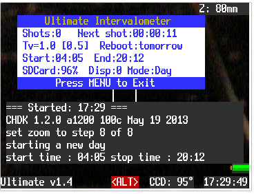
Once you have CHDK installed, you need to install the Ultimate Intervalometer script which will be the brains of the timelapse software. This script is great! There’s a ton of control in when you want the interval to begin and end, how many minutes you want between each shot, when the camera should reboot and more. For the most part I left everything defaulted, and set the interval to 7 minutes (a custom time I had to code into the script). Since I’m using a timer to control the solar battery load, I didn’t need all the other start/stop/reboot features for this project. You’ll want to have CHDK load the Ultimate script upon startup automatically, then it should start taking photos at the interval you set. Once you have CHDK and the timelapse script working on startup, then you’re past one of many hurdles 🙂
Step 2: Get the AP and 4G LTE setup
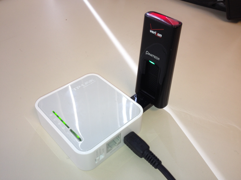
I chose to go with the TP-LINK TL-MR3020 router for a few reasons. Mainly because I know when I power off the USB cable, the 4G card is off too. This saves tremendous amount of battery. I also knew it could be reflashed to run OpenWRT, which would give me a little more control over the device. First step here is to get OpenWRT running on the device and log into it via SSH. Once logged in, there’s a few things we need to do:
- Connect to the AP via WiFi and browse to the TP Link’s HTTP IP (http://192.168.1.1)
- After you set an admin password, change the TP Link’s IP to 192.168.1.254. This way we know what it is and can also access it from the home network. But you can use whatever IP you want.
- Limit the DHCP to 100 or something
- Adjust the hostname
- Adjust the timezone
- Plug into your home network and ssh to device
- Run reboot
- After it’s rebooted, make sure there is a gateway configured on the device and run opkg update
- Once the update is done, run opkg install kmod-usb-net kmod-usb-net-rndis kmod-usb-net-cdc-ether usbutils udev
- After the installation of those packages is done, plug in the 4G USB modem
- Type dmesg and look for the following lines to indicate it found it plugged in
- [ 841.500000] cdc_ether 1-1:1.0: eth1: register ‘cdc_ether’ at usb-ehci-platform-1, CDC Ethernet Device, 12:34:56:78:90:12
[ 841.510000] usbcore: registered new interface driver cdc_ether
[ 841.610000] usbcore: registered new interface driver rndis_host
- [ 841.500000] cdc_ether 1-1:1.0: eth1: register ‘cdc_ether’ at usb-ehci-platform-1, CDC Ethernet Device, 12:34:56:78:90:12
- If it all looks good, run the reboot command again
- When it reboots, ssh back in. To double check things are OK to this point, run dmesg again and look for the CDC Ethernet Device
- Run vi /etc/config/system and verify the zonename and timezone match your regional area. Also verify the hostname is set here.
- Run these commands:
- uci del network.wan
uci set network.wan=interface
uci set network.wan.ifname=eth1
uci set network.wan.proto=dhcp
uci commit network
- uci del network.wan
- Verify they saved by running cat /etc/config/network
- This sets up the WAN interface as eth1 (the 4G USB card) and allows for DHCP
- Run the reboot command again, and ssh back in when it’s rebooted.
- Run ifconfig and look for eth1. Should probably have a 192.168.32.50 address
- Then run vi /etc/config/wireless
- Comment or remove the option disabled 1 so that wireless will be enabled
- Then configure the rest as such
- config wifi-iface
option device ‘radio0’
option network ‘lan’
option mode ‘ap’
option ssid ‘YOUR_SSID_NAME’
option encryption ‘psk2+ccmp’
option key ‘YOUR_SECURE_WIFI_PASSWORD’
- config wifi-iface
- Save and back at the command line type wifi
- Using a laptop (or cell phone) you should see your SSID pop up. If so, then so far, so good!
After a ton of research, I finally found someone who gave a hint as to how to get this 4G USB card to connect to the web. Using the program Wireshark I found that if you access http://192.168.32.2/condata?action=connect, then the card connects to the internet. There’s nothing else to it! No “modems” to dial and sync with, nothing! So I created a startup script that simply uses wget to get http://192.168.32.2/condata?action=connect. In the same startup script, I also forced an NTP update so that the time on the system was correct.
vi /etc/rc.local
(sleep 10; wget http://192.168.32.2/condata?action=connect -q -O -)
(sleep 10; ntpd -q -p 0.north-america.pool.ntp.org)
I also added a few other scripts to allow control of the internet connectivity if and when I needed to:
vi /root/connect.sh
#!/bin/sh
wget http://192.168.32.2/condata?action=connect -q -O -
echo ""
echo "done"
echo ""
vi /root/disconnect.sh
#!/bin/sh
wget http://192.168.32.2/condata?action=disconnect -q -O -
echo ""
echo "done"
echo ""
vi /root/hourlyCheck.sh
#!/bin/sh
wget http://192.168.32.2/condata?action=connect -q -O -
Then, make those scripts executable by running:
chmod +x hourlyCheck.sh
chmod +x connect.sh
chmod +x disconnect.sh
Finally, add the hourly check to the cron. What this does is run the connect command. If the internet is already connected, it’ll ignore it. If it’s not connected, it’ll connect it up. I use this to make sure I stay connected to the internet in case of any problems that disconnect it (particularly over the air reset commands. Thanks, Verizon!)
crontab -e
0 * * * * /root/hourlyCheck.sh >/dev/null 2>&1
As a final test of the whole Wifi + 4G LTE setup, I unplugged the device, then plugged it back in. After the system boots up, it should be connected to the internet automatically. Test this with your laptop or cell phone.
Step 3: Time to hack the hardware:
First step, let’s learn our power requirements! The end goal is to have this whole setup run on a (big) battery, and have it recharge via Solar. We now have the camera’s firmware setup, and the 4G Wifi Setup, now we need put all this stuff on the bench and try to make it as automated as possible. Once automated, we’ll put it on a meter and check the current during various phases of the startup and sending process.
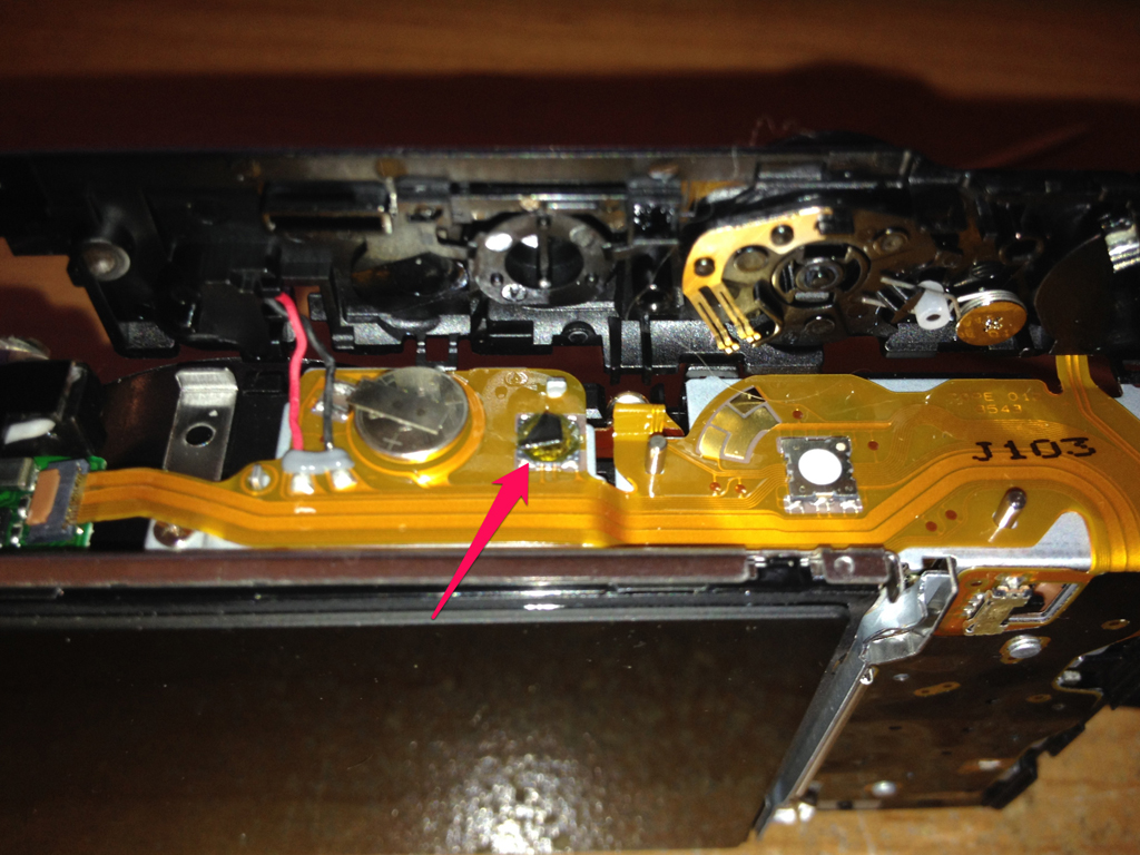
First up, getting the camera to power on automatically. My inital going-in idea was to solder a wire to the power button. THis would allow me to short a relay and power the camera on. Well, I’m not good at surface soldering, especially when it involves that yellow ribbon plastic surface. So after some trial & error and almost melting the plastic, I played with the idea of just jamming a piece of plastic on top of the power button disc. Once the plastic was in place, I inserted the battery, and removed it, and re-inserted it. Sure enough, the camera powered on every time. Downside, this may break the cheap tin popup disc, but I didn’t care. Score! Automatic power on!
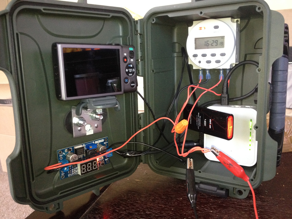
I then took the camera with dummy battery, the wireless AP, the voltage converter and the battery and hooked it all up to my multimeter. The wiring is a little messy, but I wanted to measure how much current draw there was on the battery. This will help out our math to figure out what size battery and solar panel to buy.
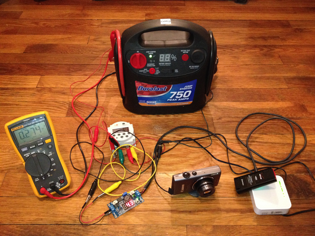
Here you can see that with everything powered on (Yes, I used a 12V car battery jumper), the average draw was 274 milliamps. Not too bad – until you start to count up the Amp Hours!
I don’t have a schematic for this setup, but essentially the timer requires it’s own constant 12v. This is what keeps the timer on. Then the timer switches the positive leads of the circuit – much like a lightswitch. So I split the 12v from the battery into the timer and into the switched side. The 12v then goes to the voltage converter where I step it down to 4.3volts. 4.3 was the voltage the camera required, and it just so happened that the AP could use 4.3 as well. Sweet – I didn’t need 2 voltage converters! It looks messy, but it’s a simple setup.
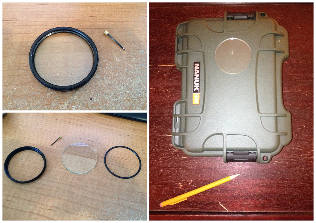
Once I felt comfortable with my current draw and rough idea of wiring, it was time to focus on the case and putting this all together. The first step for me was to measure the camera and the case, and try to dry fit it all together. Admittedly, I’m not an expert at this whole thing, so I kind of winged it. I measured maybe 10 times, then nervously made my cuts. This logic goes for every step below!
Remove the UV filter from the metal housing, and dry fit it to the flattest, most center point on the top-half of the case.
Feeling pretty comfortable with its placement, and relative “flatness” of the case, I went ahead and cut a hole in the case that was just a tad smaller than the lens, but a tad larger than the Canon lens assembly. I scratched up the plastic a bit around the hole so that the Goop would have more to grip to. I then applied a generous amount of Goop, and gently pressed the lens on. Once I had a good solid seal all around the outside, I then used Q-Tips to remove the excess Goop overflow. Goop is amazing stuff! It has a certain amount of flex to it, and can be removed from the glass with rubbing alcohol. So if I missed a dry spot, it was easy to remove. All the while it kept a waterproof seal on the case.
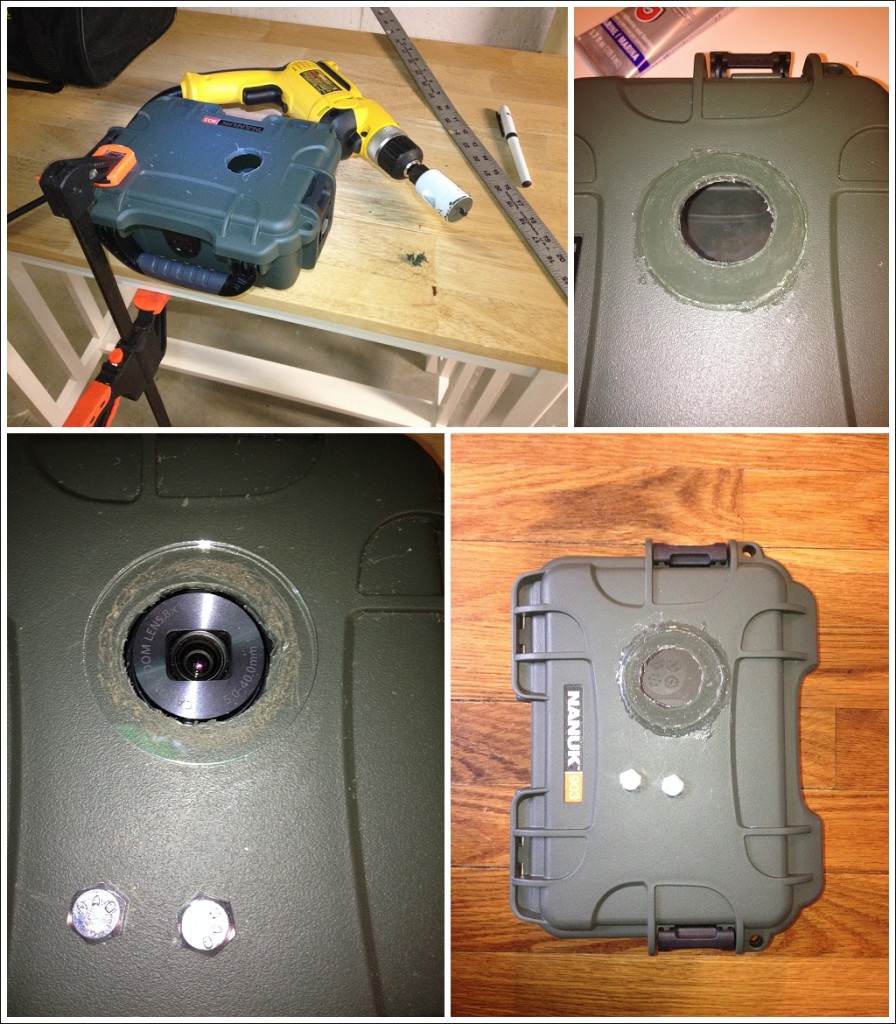
I let the Goop dry overnight to make a secure bond to the glass and plastic. It was then time to figure out how to mount the camera to the case. I ended up getting a ”L” bracket from the hardware store and attached the tripod mount to it using 1/4-20 screws and nuts. I then used the rubber washers against the case to create a water tight seal.
Once the camera was in place, I dry-fit where I wanted the other components to be. Once they looked like they were in a good spot, and the door could close (most importantly), I took some heavy duty velcro and secured the WiFI AP and the timer to the back of the case. I also velcro’d the voltage converter to the front of the case. The positioning you see here worked best in that nothing was interfering with the camera. Once all was velvro’d into place, it was time to wire it all together. This is the same wiring pattern as was described above.
Step 4: Figuring out solar power
With everything in the case, it’s time to figure out what kind of solar panel and battery we need. This is where the math gets interesting – and even sometimes contested. Ultimately I ended up asking a question on electronics.stackexchange.com to get some help. Here’s what I know:
- I know I need 12 volts DC as a power source
- I know my average current is 275mA
- I know I want the timelapse to run for 9 hours a day
- I know the solar battery controller has about 10% loss
- I know I want to have a 1 day battery reserve for those days where the sun isn’t out
- Where I live, I know my solar insolation is 4 hours average. Find yours at (http://solarelectricityhandbook.com/solar-irradiance.html)
So the math lays out like this:
Power consumption:
12V battery x 275mA current = 3.3 Watts (W) x 9 hours a day = 29.7 Watt Hours (Wh) + 10% solar controller loss = 32.67Wh
To account for the 1 day reserve:
32 Wh x 2 for 1 day reserve = 64Wh
For battery capacity:
64Wh / 12V = 5.3Ah battery x 2 (for the 1 days reserve) = 10.6 Ah battery (I rounded down to 10Ah)
To size the solar panel:
10Ah x 12v = 120 Wh nominal. 120 Wh / 0.90 solar charge efficiency (10% losses) / 4h insolation = 33.33 W panel. (I rounded down to 30W)
So after a month of crunching numbers, numerous spreadsheets later, and finally asking the question on StackExchange, my math all added up to be about the same! Not too bad! Also, it’s amazing to me at how much power is needed to run a small project like this!
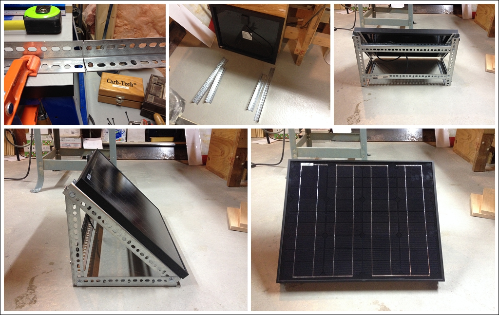
Ok, time to mount the solar panel! The answer on StackExchange also indicated that I should angle my panel roughly to the angle of my latitude. For me that’s 42, so I went with an easy 45 degree angle. After figuring out my Right Triangle calculations, I went to the hardware store to pick up some perforated angle iron. Brought it back home and started cutting my right triangle pieces, and bolted it together. Nice coating of high heat matte black spraypaint and it’s ready to go!
Time to take it outside and see if it works, and if it’s charging the battery!
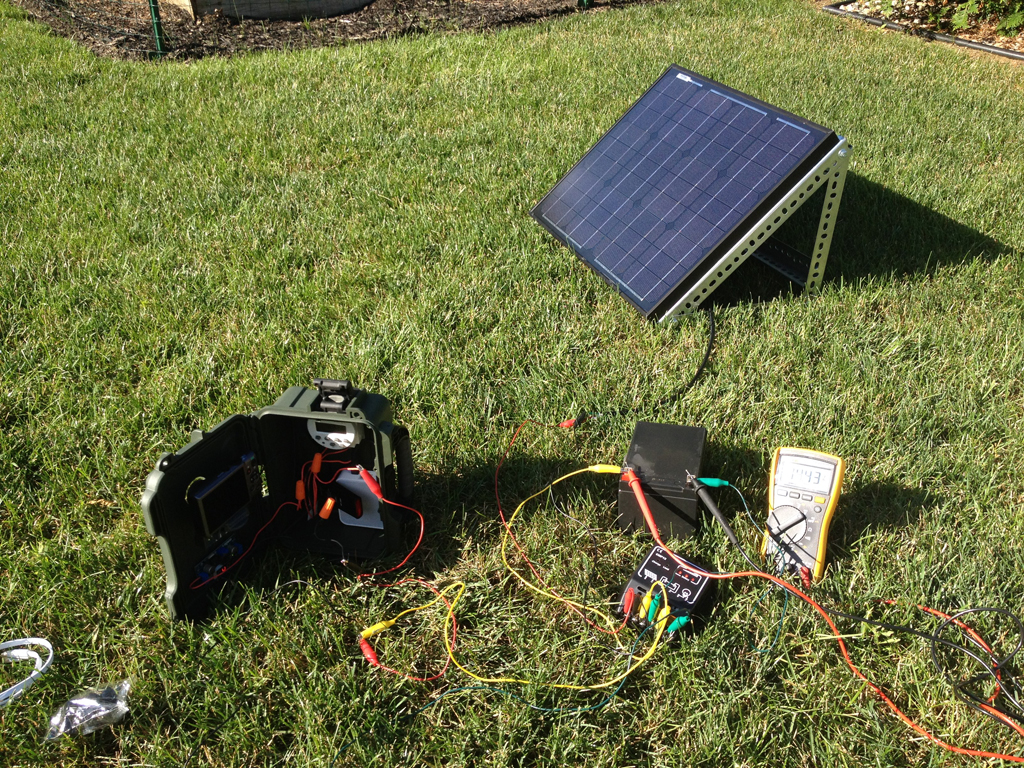
14.43 volts, sweet! That means the charge controller is doing it’s job and limiting the voltage to the battery so it doesn’t cook. Speaking of the battery, time to look at that. I added some plywood to the bottom of the solar panel mount, which created a small shelf for the battery to sit on. I went to the store and bought a plastic cereal case. This was a perfect size for the battery and solar charge controller to sit in. It was pretty water tight, but I ended up caulking it to be extra safe no water got into the battery area!
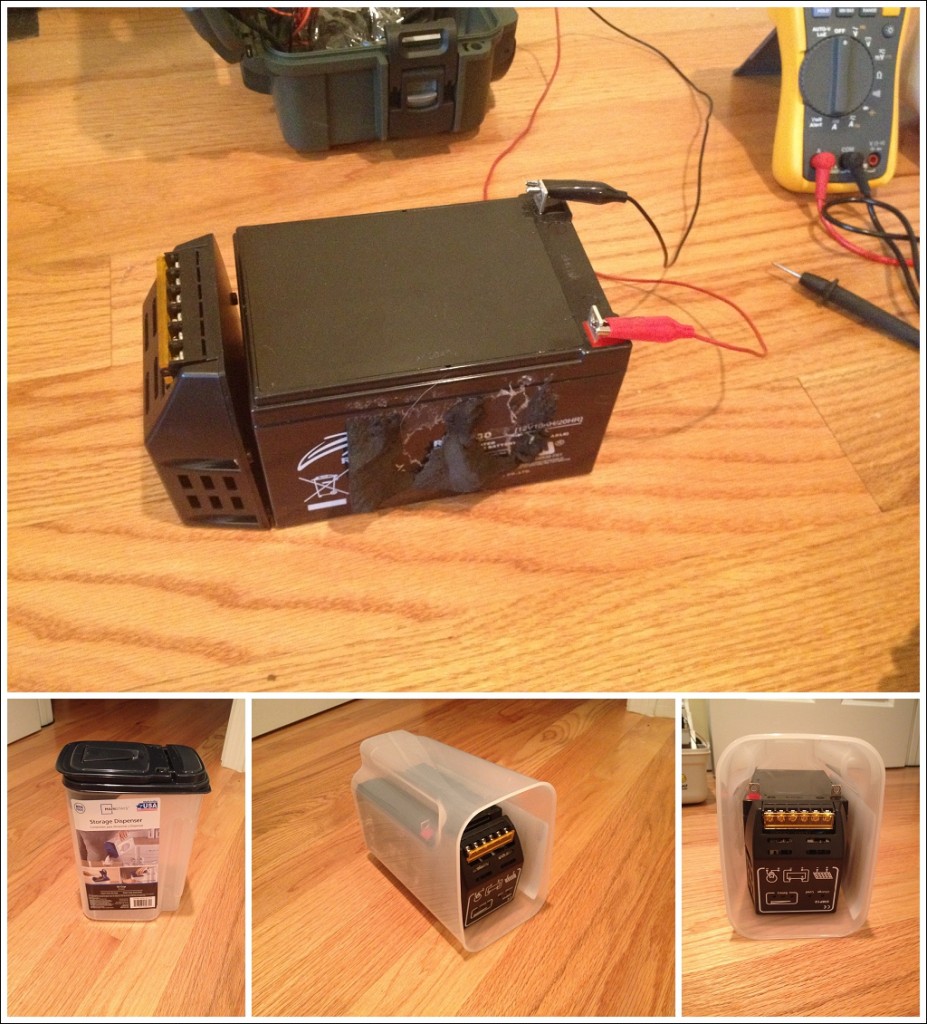
For cable pass throughs, I drilled some holes into the top of the plastic container and added the waterproof glands.
While I was installing the waterproof cable glands, I decided it was time to figure out how to get the cables into the waterproof case. We all know rain and water flows downwards, so the best bet to eliminate the possibility of water getting into the case was to have the gland on the bottom of the case.
Step 5: Mount it in the field!
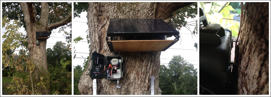
Finally after months of planning came the big day to hang the camera! Since its a construction site, there was no place to mount it other than on a tree. So I grabbed my ladder and went to work to get the solar panel / battery combo piece mounted. This part was tricky! Balancing on a ladder, with a somewhat large solar panel in hand, trying to screw it into the tree. Probably should have had 2 people on a ladder up there helping me! No worries though, I ended up getting it mounted.
As for the camera, I wasn’t sure how to mount it in a manner that would be at its most waterproof. I also wanted to mount the case to the tree from the inside – I wanted the mounting to be hidden, locked away and difficult to remove from the tree in case anyone became interested in my project, too. Again, I kind of winged it and used more rubber washers and long drywall screws. This is where I lucked out! The curve of the plastic in the back didn’t allow for a 100% tight fit for the rubber washers. I ended up not making a pre-drilled hole in the plastic case, I just drilled the screw straight into the plastic case & the tree. So I think where I got lucky is that since there was the groove in the plastic against the drywall screw also created a tight seal, which kept water out. I gave the mounting job the water bottle test before leaving (where I dumped a full bottle of water behind the case). No water came in to the case – awesome!
Step 6: Final Steps
I double-triple checked my timer was set correctly for the on & off times for the days of the week. I then added a padlock to the case, closed it up, and let it do its thing! I can’t tell you how excited I was the next morning to get the automatic “Timelapse is awake” email! That’s when I knew my months of design, planning, and building worked!
Lessons learned:
Ok, so it’s one thing to have it setup on the bench, or in the backyard. It’s another to have it 40 minutes away from you when something goes wrong.
Here’s some lessons learned with this timelapse rig out in the world:
- Don’t buy a waterproof case that has a curve to it, because the Goop and the UV Filter didn’t fit as snug as I would have liked. The Pelican cases look to be nice and flat, so if I were to do this again, I’d try Pelican.
- If you change your Verizon Wireless data plan, they’ll send a reset command to the device. Make sure you have an hourly cron task to restart the internet, otherwise you’ll be down until the next day (or until you drive out there)
- Make sure you use long screws to mount to the tree. I ended up having to get to the battery recently, and 2 screws snapped off the tree. Thankfully I had the drill and more screws with me!
- When making the right triangle for the solar panel, make it bigger than the panel is! This way you can get your hands to the battery and shelf at eye level! Right now if I have to work on the battery, the angle is awkward and I can’t see what my hands are doing.
- Empty the SD card every so often. The CHDK firmware was acting funky on me until I cleared out photos. Then its been good ever since.
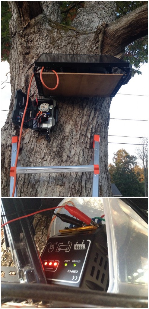
- Make sure the timer is set to turn off. I made this mistake which ended up killing the battery and requiring a recharge from the car (photo below)
- Save some of those Silica packets you get in certain packages. They’re great for keeping moisture dry on the inside of the case!
- Don’t plan for 1 day’s worth of battery reserve. If you have 2 days of cloudy skies, the battery will die on the 2nd day of cloudy skies. It’s no fun!
- Add a 3rd waterproof gland to the battery case for emergency charging. That way I can hook up the car battery to the panel battery without having to break that caulked waterproof seal! (photo below)